One of the items we cover at our training sessions, and one which a lot of service engineers find most interesting and illuminating, is electrical troubleshooting.
This could be because what we cover is a bit of a ‘myth-buster’… electrics isn’t always as complex as you might think – it’s just mostly logic. As long as you can work safely, your client site doesn’t have any strict non-electrician policies (we know some do), and you have the knowledge and confidence (this is where we come in), then you can try and find an electrical problem on one of our machines… plus, equally importantly, what to do about it.
The first thing is to explain is that all of our electrical products use what’s called a DOL (Direct-on-line) starter – basically, it’s one of the simplest types in that once the ‘control circuit’ is complete, a magnetic field is created by the coil inside the contactor, which then ‘pulls in’ the contacts to immediately connect the motor to power to start it up.
Electrical troubleshooting – Hints & Tips
What is the ‘control circuit’? In our products, it comprises the following:
- Pressure switch (Danfoss or Bailey & Mackey) – normally-closed when the pressure is below cut-in, a circuit is made between the terminals on the switch which then opens once the cut-out pressure is achieved;
- Thermal overload – a normally-closed device below the contactor starter, which opens if the motor is drawing a too-high current, cutting power to it;
- Emergency stop – this is a normally-closed relay which, when the red button is pushed on the enclosure, opens to cut the motor; and
- On-delay timer (most compressors, all AVBP) – an electronic device which is incorporated to prevent the compressor cutting in immediately (which may prevent fast emission of water when a sprinkler head activates), or the AVBP from hunting/chattering; once the on-delay time has elapsed, the current will pass through to the contactor.
What may indicate that a compressor, for example, has an electrical problem? The main symptom may be that it doesn’t start at all (no noise), or when it stops there is no hiss from the unloader valve on a CS-type switch. In this case, this is what we would suggest (remove pressure switch and contactor enclosure covers):
- With the power on, and using an insulated tool, push in the central black bar on the contactor. If the pump starts and runs normally, then the incoming power supply is OK, so the issue is most likely the control circuit. If the pump does not run, then check the incoming power supply – this may prove a lack of power or phase, otherwise if that is OK then the most likely explanation is that the pump motor/windings are faulty.
- If the above test points to a control circuit issue, then the first test depends on the model, and for this you will need to isolate power and use a continuity tester:
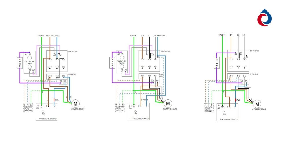
- 230v: use probes between incoming live 1L1, and #15 on the on-delay timer (see image below)
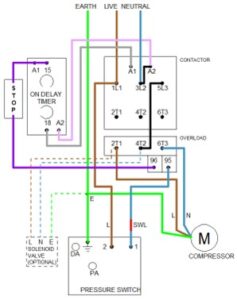
- 400v with neutral: use probes between incoming neutral and #15 on the on-delay timer (see image below)
- 400v no neutral: use probes between incoming live 1L1 and A1 towards rear-left of contactor (see image below)
- If the above test proves a circuit then it’s most likely to be the on-delay timer (on models where this is included); the on-delay timer is a sensitive electronic device and therefore one of the more likely components to fail after some time.
- If the above test shows no circuit, then this is why the contactor will not ‘pull in’, so now check each component…
- Pressure switch: check continuity between the connected wires on the switch; if not, is the system above cut-out pressure, or is the switch turned off, or can you check the orifice in the connector? If all clear, then the switch could be faulty, although in our experience this is not a common problem.
- Thermal overload: check continuity between 95 and 96 on the front-right of the overload; if no circuit then the overload may have tripped – press reset and check that the small switch is set to A(uto).
- Emergency stop: check continuity between the top and bottom connections, although again this would be a rare problem.
- On-delay timer: you cannot check this with power off, so if you suspect this is the problem then ask us for a brief instruction to wire this out of the circuit to prove it is working or otherwise.
- You may also refer to the wiring diagrams and check each wire joining the components (if you don’t have this, simply head to our Downloads web page, and the ‘Need Help?’ QR code sticker on more recent products will take you straight there’.
The above will not solve every problem, but hopefully it will allow you to make a start and eliminate some possible causes. Of course, we are more than happy to take a phone call if you are on site and need help. Happy problem-solving…
230v
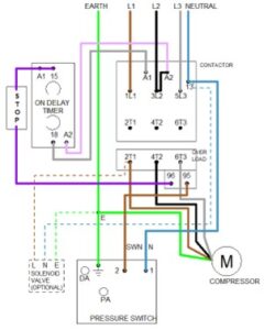
400v+N
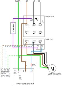
400v no N