When customers attend our free training sessions, we broadly cover selection, installation, commissioning and troubleshooting for our key products – air compressors, pump initiation boards, Zone Guardian, Alarm Valve Booster Pumps, Residential and more!
One of the biggest ‘bugbears’ most customers raise is setting Bailey & Mackey 1381V pressure switches! Who knew that something so small and (supposedly) simple could cause so much angst, amongst even the most hardened engineers? So to help, we have pulled together some of our own setting tips – we don’t profess that this is a ‘one size fits all’ perfect and only way to do it, but we’ve found it works for us – and even some of the most experienced attendees on our training course do leave with a different perspective, even ‘enlightened’!
 So, first of all some general guidance:
- Always electrically isolate the switch when setting (although we recommend only the use of insulated tools).
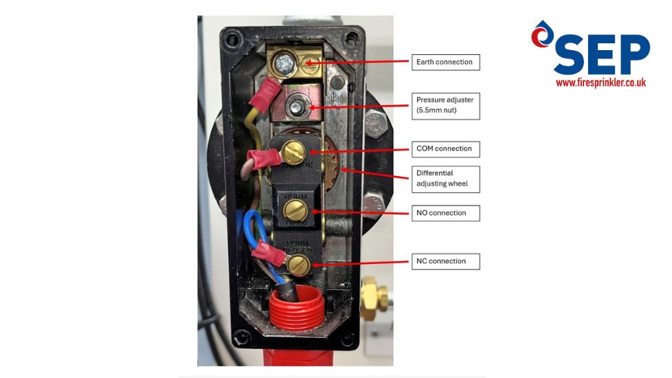
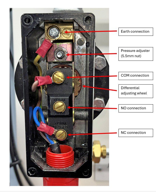
- Both the pressure adjuster (5.5mm nut) and differential adjuster (notched wheel) wind clockwise to reduce, and anti-clockwise to increase. This is NOT marked on the switch! Also note that turning too far anti-clockwise could permanently damage the switch.
- Both have a ‘scale’ which is approx. ¼-turn is approx. 10% of switch range, so on a 14 bar switch, ¼-turn is approx. 1.3 bar – this makes the switches very sensitive to adjustment, and adjusting by say 0.1 bar can be tricky.
- When switching, there is a light ‘click’ which can be difficult to hear when there is background noise – a simple continuity tester with buzzer can be very useful.
- If using the NC connection, a click whilst turning anti-clockwise indicates the cut-IN pressure; a click whilst turning clockwise indicates the cut-OUT pressure.
With this in mind, this is how we would do it:
- Start by turning the notched wheel clockwise until it stops, and turning the pressure nut anti-clockwise a full turn (minimise differential, maximise cut-out).
- Turn on the jockey pump and then turn off manually when pressure is slightly above required cut-out; then open test valve to drop pressure to the exact required cut-out.
- Now turn the pressure adjusting nut clockwise until it clicks (or until your continuity tester buzzes).
- Turn pump back on, drop pressure using test valve and observe pump’s cut-in and cut-out pressures.
- If you need to increase the differential, start with 12 clicks of the wheel anti-clockwise and test cut-in and cut-out again.
- Once the differential has been adjusted, either or both of the cut-in and cut-out may drift. Adjust to the correct differential first, and then go back to the pressure adjusting screw, making small increments up or down.
- Bob is (or should be) your uncle!
One thing we know from our own practice, and feedback from our attendees who are out in the field, is that seemingly small adjustments may have big impacts, and switches can be very sensitive. If you are struggling, please be assured that this is not unusual at all, and pressure switch setting can be as much of an art as a science.
Also, continue to ‘watch this space’ as we will soon be offering a ‘1381 adjusting tool kit’ to make life that little bit easier. If you are interested, then just let us know by dropping us a line.