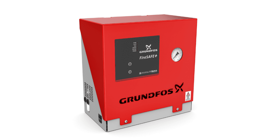
In an effort to better ourselves (we do try!), last month we attended a day’s training session at Grundfos Sunderland, which is where all FireSAFE+ booster pump sets are assembled and tested – in fact, the session was made so much better with the joint attendance of several of our customers from North Wales as well (and if you’d like us to arrange some similar training for your team, then contact us here – we can arrange a session at Sunderland, and shortly we will be able to host sessions in our own training room in Stockport).
So now, whilst we are not the experts, we are much better placed to assist all of our customer with any FireSAFE+ installation, commissioning and fault/maintenance questions.
What has become clear over the last year or so, is that the ‘new world’ of domestic and residential booster pump sets is very different to the old – gone are the days of banging in any old pump with a resi-riser (or just a flow switch or pressure switch) – with the introduction of computer-controlled functions, multiple fault signalling – and, uniquely to Grundfos, historical data-logging.
We thought it might be useful to summarise some of the issues which we have come across over the past few months, to help our customers successfully install, commission and maintain these advance booster pump sets.
- As well as the booster pump set, a solenoid valve cooling line (which may or may not have been pre-fitted) a flow switch, and a water-level switch if using a tank, are all essential to a BS9251:2021-compliant system.
- The installation file allows you to easily program into the unit your own installer details, as well as the unit’s unique location, so that the log files contain this information. We can help with this.
- Once installed and wired up (noting the wiring requirements for the flow switch and tank level switch) there are just FOUR things to do:
-
- Set the pressure switches – they are factory set, but chances are you will need to tweak to site-specific conditions;
- Check/set the date and time, using a USB stick
- Set the auto-test timer, using the keypad
- Set the annual service reminder, using the keypad
- Some of the more common installation/commissioning issues are (sometimes the LED can be confusing…BUT a log extraction gives absolute clarity):
- FIRE mode when no fire: flow switch not wired in, or wired incorrectly.
- Fault LED, 3 flashes: water level switch not fitted, or not linked out.
- Fault LED, 2/4/5/ flashes: pressure switches not set the same, or not adjusted to local pressure.
- Fault LED, 6 flashes: excess jockey pump, may be leak.
- Fault LED, 9 flashes: cooling line not fitted, or not draining.
WE ADVISE it should become second-nature when visiting any unit on site, to download a set of logs – anyone who has attended Grundfos training will have received a USB stick, and we also have them available should you require. Adaptors from the USB stick to mobile phones are available, should you wish to read the logs on site and do not have a laptop. The logs should be kept on your files for reference should the need arise. All technicians responsible for installing FireSAFE+ should carry two USB sticks – one for the installation file, and one for extracting logs. We have USB sticks in two colours for this purpose, so just ask if you need some.
If you have any questions on the FireSAFE+ range, please contact us [here] and Cameron or Rob will be pleased to help.
If you want to go one step further and arrange training for yourself or your team, get in touch and we can arrange this too!