Going back even just four to five years, air maintenance devices (AMDs) were just an occasional product for us. Over the past couple of years demand has increased many-fold, recently to the point that we were the main cause of our national distributor completely stocking out of 3/8” air regulators for over a month!
What is the purpose of an air maintenance device?
In a nutshell, they are designed to control the ‘excess’ air held by a larger compressor system, regulating both the amount (flow) and pressure of air entering the fire sprinkler system and maintaining the correct pressure for the particular type of alarm valve installed.
What are the key components of an air maintenance device?
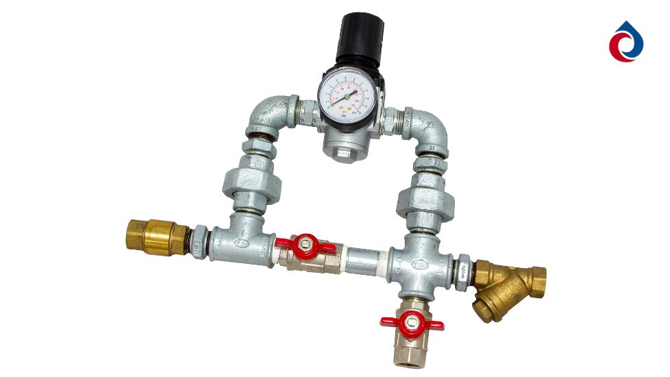
- Inlet strainer: to prevent any pipework contaminants entering the regulator or orifice, which would prevent proper operation.
- Fast-fill bypass valve: to allow quicker refilling of a system which has been depressurised for maintenance/repair.
- Regulator: to allow fine control of the air pressure entering the sprinkler system.
- Restricted orifice: to ensure that, upon a sprinkler activation, excess air flow does not interfere with the alarm valve operation.
- Outlet NRV: to prevent backflow of air from the sprinkler system back to the compressor.
- Test outlet: to allow compressor switch cut-in and cut-out to be set and tested, without affecting the sprinkler system.
We think that one of the key reasons for AMD growth is the increasing use of low pressure dry and pre-action alarm valves (for example the Victaulic NXT); in turn, one of the key drivers for the growth in low pressure alarm valves is simply that the lower the air pressure required in a sprinkler system, the fewer and smaller the leaks, the lower the demand for air and – in turn – the less expensive and energy-intensive a system is to run.
Tips for easy installation and set-up:
- An AMD must only be installed on a compressor with receiver tank; never install this device on a compressor without receiver.
- The outlet from the compressor should feed into the strainer, then the AMD non-return valve is system-side; there is usually no need to fix/bracket the AMD if installed to solid pipework, but do fix to a solid surface if using flexible hoses.
- We recommend installing an isolation valve between the AMD and the sprinkler system (by the way, NEVER use the safety release valve for this purpose), for easier setting and maintenance.
- Close both the above isolation valve and the bypass valve, lift up the regulator knob (you can see a red ring below) and turn all the way anti-clockwise to minimise the pressure.
- Turn on the compressor and charge the receiver with air.
- Turn the regulator knob clockwise slowly to increase the pressure, using the gauge on the regulator as an approximate guide (bearing in mind that these small gauges are not as accurate as larger system gauges).
- Once the pressure has been set locally, and when any other parts of the sprinkler system are ready, open up the isolation valve to allow air to enter the system; you may also open the fast-fill bypass valve BUT do not leave the device unattended, and close this valve once the system pressure approaches the required level.
- Once settled (the compressor may cut in and out a number of times), double-check the pressure using a system gauge (ideally calibrated) and if you need to tweak the pressure then do so very slowly using the regulator – once complete, push down the knob to lock (red ring no longer visible).
Hopefully you have found the above brief guide helpful to your system design and operation. If you have any questions, or would like to ask about pricing and availability, please Contact Us .