As reported some time ago we cannot over-stress the importance of installing compressors to a solid wall or floor with strong and suitable fixings – our Operating & Maintenance instructions labour the point, advising that all four holes should be used with strong and tight M10 bolts.
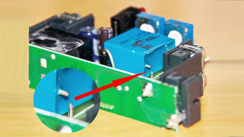
It’s strange how things seem to arise in batches, but towards the end of last year we had reported to us several instances of failed electrics. Almost all of these were found to be failed on-delay timers which in turn were largely shown to have been caused by vibration being transmitted from the compressor pump to the starter box mounting. In one particular site visit, two compressors were wall-mounted side-by-side – one vibrating and one not – which allowed a perfect demonstration of the issue.
The on-delay timer is probably one of the most vulnerable components, as it is after all a relatively delicate PCB with a number of soldered electronic components. We could leave it out, and on some 3-phases models we have to (or customers request that we do). However, it’s important to recognise that this timer satisfies a key requirement of BSEN12845 by preventing the compressor cutting in immediately there is a drop in pressure which otherwise could cause a delay in the time taken for water to emit from a sprinkler head following activation.
We do mitigate the effect of motor vibration transmission as much as possible, by using heavy duty rubber buffers under the compressor mounting plate, but if the frame itself is not solid then the vibration will transmit.
Probably the easiest way to check this is to run the compressor with the contactor starter box lid open – obviously there are live electrics, so never touch anything – the contactor and timer should not display any noticeable vibration.
The short videos in the previous article about correct compressor installation, demonstrates what you should be looking for.
Take a look at our Compressor range

